mm-hist.htm; updated: 01 January 2007

History of the
MicroMag System
Since the beginning of my modeling career I was interested in smaller
models, the biggest internal combustion motor I flew was a 1.5 cc Webra Record
diesel, the others were the 0.8 cc Webra Piccolo diesel and the Cox PeeWee 020.
I started competition flying with some A-1 gliders but mainly in Coupe d' Hiver
rubber. In this class I became twice the national champion. Both classes are
the smaller version of the World Championship classes A-2 and
When I started RC flight money was a bit of a problem, so I tried to build some
gear of my own. Not too successful at that moment but I made some flights with
the illustrious galloping ghost system. This is basically a single channel
system where the transmitted tone is pulsed. Right-left control is achieved by
changing the on-off ratio, where e.g. right can be on and left is off. Changing
the pulse frequency could be used to control up-down. The
The
The magic of the Galloping Ghost system was that it worked! And it was
lighter than any other 'multi' radio system at the time. But, the control was
far from subtle. The single channel variant was used by several suppliers in
the 60's like
A photo of Bentert's receiver and
actuator as published in Aeromodeller March 1964
This inspired me to make one myself my actuator weighting
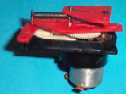
In 1972 Dieter Engels published the do-it-yourself PicoProp system in the
German Magazine 'Modell'. This was a single channel analogue proportional radio
with a special transmitter and a feedback servo. He integrated the good but
simple radio and the servo electronics on one PCboard, where also the clever
servo mechanics made from a Swiss TO5 motor with 1:141 reduction box and the
remains of a carefully disassembled potentiometer. This complete unit weighed
about
I made this system and flew it in my first R/C electric flights in 1974.
The PicoProp single channel board
with gearhead for the servo.
It is a pity that I don't have the system itself anymore or even a photo
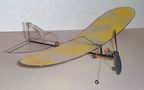
of mine. The model, with the fuselage rebuild is still flying, now with a
Speed-300 and a 3:1 reduction driving a 6 x 5.5 Graupner speed prop. The model
weighs now
The Sub Mini as it still flies now.
Around 1985 I started again with the LM1875, an IC from National
Semiconductor meant for toy R/C. It had an AM superhet radio with decoder for 2
channels and circuitry to adopt two extra switched channels. Super for
lightweight R/C at the time, I thought. I designed very nice receivers for this
IC that worked but not very well. Some small commercial receivers have been
made with it but none were a real success as far as I know. The Rx was
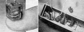
In 1994 Herbert Hoger published a small FM receiver of
The LM1875, the Herbert Hoger
receiver and my version with servo electronics
I build it and was not entirely satisfied. The Rx had no IF filtering at
all and a ceramic discriminator, a combination that is not good in blocking
interference. Also the IC for the Rx was rather big as it was intended for
double conversion and only a small of the IC part was used. In that time I came
into contact with Wijnand de Joode a very good FreeFlight indoor scale builder
and flyer. His dream was to build and fly Peanut scale models (
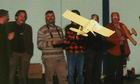
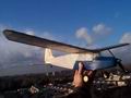
An action photo of the FIKE-E in
flight, Me at the controls and Wijnand de Joode on my right.
The Fike is a very fine flyer, although it doesn't have any dihedral the model
turns with grace.
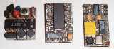
I started to design my own Rx along the Motorola Mc3361. I found some
very small ceramic IF filters and LC discriminator filter. This Rx with the
servo electronics was a direct success. All parts were carefully picked for low
voltage performance as the weight of the batteries was (and still is) the
remaining barrier for smaller and lighter planes.
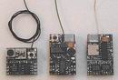
Two sides of the first generation of
the MicroMag receiver together with the current version.
The first plane was a PonyMax build by Wijnand de Joode. It is a Czech
homebuilt with simple lines and good proportions,
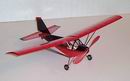
The Pony Max, build by Wijnand de
Joode, flown by Rick Ruijsink
This power combination is still used in the majority of my models. Its
first flight was at the 1996 fair in Sinsheim, where the European Slow flight
really took off. Walter Scholl flew his superb
Rainer Mugrauer flying between the
legs of nine tables
There was so much interest in the radio that I was forced to plan
production. That proved to be more time consuming than I expected. The design
work on servo's and radio seemed relatively easy, now all the difficult parts
were working properly. One of the problems that I encountered with the first
hand made pre-production models was one of compatibility. All the electronics
except the speedcontroller were integrated on one PC board, which meant that
the channel allocation was fixed. As Graupner/JR always has throttle on channel
#1 and e.g. Futaba always on # 3, it would have been required to make two
versions. With the fixed crystals this would explode the number of variants
that I and/or a dealer would need to satisfy his customers. I also had one
client for whom I made the Futaba version and when he moved to Graupner I had
to change his receiver back. The other snag was that the neutral timing of the
channels had to be adjusted by hand through the placement of individually
picked SMD resistors, as the non-computer transmitters have a trim range that
cannot cope with the tolerance in the normal timing resistor-capacitor. A few
of the pre-production radio's went to the R/C CO2 guru
in the USA Henry Pasquet.
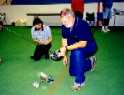
Henry Pasquet with a handful of CO2 models.
His positive and critical comments were very welcome, he brought me in
contact with Bob Selman, an enthusiastic indoor flyer who is a talented,
professional microprocessor programmer.
Bob Selman with his Daisy
We discussed the problems (I don't like the euphemism 'challenges') and
Bob promised me we could solve them and he was right. It took some time but it
was worth the time. We could, after a lot of bench and later flight tests (one
at midnight under the light of a street lantern) realize all the goals.
The original Daisy.....
...... as a testbed for the
microprocessor development.
Furthermore one 8 pin IC did replace: one 14 pin, one 16 pin IC, four
transistors, two capacitors and ten resistors. The old receiver was 15 x
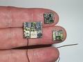
The new MicroMag reciever and
speedcontroller from both sides on my fingers.
The servo's were improved by using custom made neodym magnets and
specially orthocyclic would coils. This winding technique ensures the optimum
hexagonal wire packaging. This yields the highest magnetic field for a given
mass of copper. The amount of copper in relation to the mass of the magnet was optimized
as well. Two sizes of magnetic actuators are now in production. The small one
is
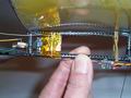
Two small and two 'big' actuators
mounted on a small balsa tray
An integration of the speedcontroller and the Rx has been considered and
tried, but sensitivity to interference increases, and the 'heavy' motor wires
will be longer, in fact increasing the weight. Also the flexibility for the
producer, dealer and buyer/user is degraded, so this idea was abandoned.
A separate small speedcontroller that is able to handle 1.5 amp was designed. Part
of its intelligence is built into the receiver, so these two go together. You
cannot use this controller with a normal receiver, you cannot use the MicroMag
receiver with a normal speedcontroller. You can use the MicroMag receiver
without speedcontroller in a CO2 model or a glider.
Update 01 January 2007
Some years after the introduction of the MicroMag system other suppliers
came with their own systems based on magnetic actuators. To name a few http://www.jmp-solutions.com, http://www.microinvent.com, and http://www.microplanesolution.com/index.htm
for 27 to 72 MHz systems for use with conventional transmitters. Or on http://www.plantraco.com/hobbies/product_butterfly.html
you will find a system on 900 MHz. The ultimate light system based on 27 th 72
MHZ AM transmitters cn be found at http://microflierradio.com.
MicroMag is not available anymore. We are currently considering a new
generation of micro radio control systems.
Copyright © 1999 Ruijsink Dynamic Engineering. All
trademarks shown are trademarks of their respective owners. All rights
reserved.
http://www.ruijsink.nl, designed by Rick Ruijsink